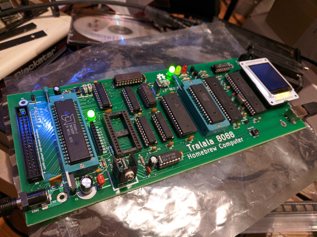
Tralala 8088 is a homebrew computer with an 8088 CPU, capable of booting DOS (MS-DOS, PC DOS or FreeDOS). It is an open source hardware project and all its software and firmware is free/libre software. It can serve as an educational board, for studying how a "real" microprocessor works, and for people, interested in retrocomputing as a hobby. Unlike other boards like the Arduino series or the Raspberry Pi, this one doesn't use a microcontroller or a System-on-Chip, but a microprocessor, which contains no internal RAM or Flash memory at all, and is not programmable in any way. Instead, it uses the system bus to communicate with external RAM and ROM chips in order to fetch and execute code. My personal reason for doing this project was to help me study and develop a cycle-exact emulator for the 8088 CPU. By attaching a logic analyzer to the board, you can examine every bus cycle, whether it's read memory, write memory, an I/O read or write, etc. You can also monitor the processor's internal prefetch queue, because that is also available on the CPU's pins. But the board can be built and tested without a logic analyzer as well, and can be used for studying and experimenting with other things, such as BIOS and firmware development, etc.
This documentation is for PCB version 1 - Jan 17 2023.
This is a single board computer, that uses only through-hole components. This makes it easy to solder and prototype extensions, using breadboards, etc. The computer contains 512 KiB RAM and 512 KiB ROM (flash) memory. It is *not* 100% IBM PC compatible at the hardware level, however it is compatible with the IBM PC at the BIOS level. In other words, you can using IBM PC's standard BIOS software interrupts for reading the keyboard, writing to the screen, and accessing the disk. However, if you try e.g. writing to the screen directly, or accessing the PC hardware directly via I/O ports, it will not work. This, however, is enough to boot MS-DOS, PC DOS and FreeDOS, as well as many console DOS programs, such as debug.com, GW Basic, Turbo Pascal 2, some text adventure games, etc. Graphical games will not work, as well as many full screen TUI applications that access the video hardware directly. This makes the hardware much simpler and easier to understand. Making a full 100%-compatible IBM PC clone is not a goal of this project - there are other projects, that do that.
The Tralala 8088 Homebrew Computer connects to a PC via an USB connection. It implements an USB serial interface device, that can be accessed via a terminal emulator on the PC side. The serial connection serves as keyboard input and display output for the homebrew computer. Writing to the screen via int 10h or reading the keyboard via int 16h works over this connection. Commands for moving the cursor, scrolling, or changing the text color and background are all implemented and are converted to ANSI ESC sequences, so this all works in a normal terminal, if you use e.g. Minicom under the Linux console (or any xterm clone), or if you use PuTTY in Windows.
The BIOS image contains a built-in diskette image that is visible as drive A, using int 13h. It is visible as a read-only device (like a write protected) diskette. You embed this image, when you're building the BIOS from source. The default image contains a small FreeDOS bootable disk, that contains debug.exe. You can replace this image with a different operating system (e.g. MS-DOS) or include different files.
An optional Arduino LCD Screen connection allows booting from an external MicroSD card. If the Arduino LCD Screen is detected, and there's a MicroSD card inserted in its MicroSD slot, it becomes visible as hard disk 0 and an operating system is booted from this disk. Both reading and writing to the card is supported.
There are two chips on the board, that require programming (flashing), before your computer comes alive. The first one is the flash chip, containing the BIOS. This can be a SST39SF040 (recommended, 512 KiB flash), or a SST39SF020 (256 KiB) or SST39SF010 (128 KiB) chip. You need a programmer, capable of programming this family of chips. Another chip that needs programming is the PIC18F4550 microcontroller. For this, you need a PIC programmer.
The programmer that I use is the Batronix BX48 Batego II. It is capable of programming both the BIOS chip and PIC microcontroller. If you don't have any programmer and you can afford buying this one, I recommend it. But if you don't have the budget, you can probably find much cheaper programmers that would still do the job. If you succeed, using a cheaper programmer, please email me, so I can add info about it to this page.
The board is powered by a 9V DC barrel jack, positive pin in the middle. There's reverse polarity protection, so switching positive and negative will not damage any components. The board should tolerate anything between 7.5V and 25V on the input. However, using a higher voltage will cause more heat to be dissipated by the 7805 regulator, so it will require a larger heatsink and maybe even a fan. All of this for no good reason - it's just more wasted energy as heat. That's why I don't recommend using more than 9V. You can even use 7.5V and then the 7805 will run even cooler, however, in this case, I recommend replacing diode D1 with a Schottky diode to achieve better regulation.
It might be possible to achieve better efficiency, especially with higher input voltage, if you replace the 7805 regulator with a switching DC-to-DC converter. There are 7805 pin-compatible ones that can be plugged directly, like this OKI-78SR-5/1.5-W36-C. Note that these can introduce switching noise and the board hasn't been tested with them, so try them at your own risk.
If you want to be able to monitor the 8088 bus and examine the actual instruction timings, you need a logic analyzer. I recommend the Intronix LA1034 LogicPort.
Thanks to Vladimir Garistov for doing the PCB layout and routing!
Copyright (C) 2016, 2017, 2022, 2023 Nikolay Nikolov <nickysn@users.sourceforge.net>